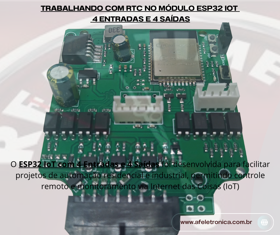
O ESP32 IoT com 4 Entradas e 4 Saídas é uma placa desenvolvida para facilitar projetos de automação residencial e industrial, permitindo controle remoto e monitoramento via Internet das Coisas (IoT). Neste artigo, será apresentado um exemplo de como utilizar o Real Timer Clock do módulo.
Características do ESP32 IoT 4 Entradas e 4 Saídas
- Microcontrolador ESP32 com Wi-Fi e Bluetooth
- 4 entradas digitais para sensores
- 4 saídas à Transistor Open-Colector para acionamento de cargas
- Conexão via protocolo MQTT e HTTP
- Compatível com plataformas como Arduino IDE e ESPHome
- Real Time Clock
Materiais Necessários, Para seguir este guia, você precisará de:
ESP32 IoT 4 Entradas e 4 Saídas
- ESP32 IoT 4 Entradas e 4 Saídas com Real Timer Clock
- Fonte de alimentação 12V ou 24V
- Conversor USB Serial
- Sensores e atuadores conforme necessidade do projeto
- Computador com Arduino IDE ou outro ambiente compatível
Passo a Passo para Configuração
1. Instalação da IDE e Bibliotecas
Antes de programar o ESP32, é necessário instalar o Arduino IDE e adicionar o suporte ao ESP32:
- Abra o Arduino IDE e acesse Preferências.
- Adicione o link de gerenciador de placas do ESP32:
https://dl.espressif.com/dl/
package_esp32_index.json
Instale as bibliotecas
RTClib para comunicação com o RTC
Wire para comunicação com I2c
2. Cofiguração do RTC
Para se comunicar com o RTC use o seguinte código.
// Date and time functions using a DS1307 RTC connected via I2C and Wire lib
#include "RTClib.h"
#include "wire.h"

RTC_DS1307 rtc;
int SDA = 21;
int SCL = 22;

//Configuração dos Pinos do módulo
int LED_BUILTIN = 2;
int OUTPUT1 = 17;
int OUTPUT2 = 04;
int OUTPUT3 = 16;
int OUTPUT4 = 05;
int INPUT1 = 33;
int INPUT2 = 25;
int INPUT3 = 26;
int INPUT4 = 27;
int SW2 = 18;


char daysOfTheWeek[7][12] = { "Sunday", "Monday", "Tuesday", "Wednesday", "Thursday", "Friday", "Saturday" };

void setup()
{
  REG_WRITE(GPIO_ENABLE_REG, BIT2 + BIT4 + BIT5 + BIT16 + BIT17);  //Define os Pinos como saída

  //inicializa os pinos como Entrada
  pinMode(INPUT1, INPUT);
  pinMode(INPUT2, INPUT);
  pinMode(INPUT3, INPUT);
  pinMode(INPUT4, INPUT);

  //inicializa as saídas no modo desligado
  digitalWrite(OUTPUT1, HIGH);
  digitalWrite(OUTPUT2, HIGH);
  digitalWrite(OUTPUT3, HIGH);
  digitalWrite(OUTPUT4, HIGH);
  Serial.begin(115200);

  Wire.begin(SDA, SCL);

#ifndef ESP32
  while (!Serial)
    ;  // wait for serial port to connect. Needed for native USB
#endif

  if (!rtc.begin()) {
    Serial.println("Couldn't find RTC");
    Serial.flush();
    while (1) delay(10);
  }

  if (!rtc.isrunning()) {
    Serial.println("RTC is NOT running, let's set the time!");
    // When time needs to be set on a new device, or after a power loss, the
    // following line sets the RTC to the date & time this sketch was compiled
    //rtc.adjust(DateTime(F(__DATE__), F(__TIME__)));
    // This line sets the RTC with an explicit date & time, for example to set
    // January 21, 2014 at 3am you would call:
    //rtc.adjust(DateTime(2014, 1, 21, 3, 0, 0));
    // rtc.adjust(DateTime(2024, 8, 21, 13, 46, 0));
  }

  // When time needs to be re-set on a previously configured device, the
  // following line sets the RTC to the date & time this sketch was compiled
  // rtc.adjust(DateTime(F(__DATE__), F(__TIME__)));
  // This line sets the RTC with an explicit date & time, for example to set
  // January 21, 2014 at 3am you would call:
  //rtc.adjust(DateTime(2014, 1, 21, 3, 0, 0));
  rtc.adjust(DateTime(2024, 8, 21, 14, 14, 0));
}

void loop() {
  DateTime now = rtc.now();

  Serial.print(now.year(), DEC);
  Serial.print('/');
  Serial.print(now.month(), DEC);
  Serial.print('/');
  Serial.print(now.day(), DEC);
  Serial.print(" (");
  Serial.print(daysOfTheWeek[now.dayOfTheWeek()]);
  Serial.print(") ");
  Serial.print(now.hour(), DEC);
  Serial.print(':');
  Serial.print(now.minute(), DEC);
  Serial.print(':');
  Serial.print(now.second(), DEC);
  Serial.println();

  Serial.print(" since midnight 1/1/1970 = ");
  Serial.print(now.unixtime());
  Serial.print("s = ");
  Serial.print(now.unixtime() / 86400L);
  Serial.println("d");

  // calculate a date which is 7 days, 12 hours, 30 minutes, and 6 seconds into the future
  DateTime future(now + TimeSpan(7, 12, 30, 6));

  Serial.print(" now + 7d + 12h + 30m + 6s: ");
  Serial.print(future.year(), DEC);
  Serial.print('/');
  Serial.print(future.month(), DEC);
  Serial.print('/');
  Serial.print(future.day(), DEC);
  Serial.print(' ');
  Serial.print(future.hour(), DEC);
  Serial.print(':');
  Serial.print(future.minute(), DEC);
  Serial.print(':');
  Serial.print(future.second(), DEC);
  Serial.println();

  Serial.println();
  delay(3000);
}
Enviando o código para o módulo de desenvolvimento ESP32 IoT com 4 Entradas e 4 Saídas
- Segure simultaneamente os botões PGM e Reset
- Solte Reset, solte PGM, neste momento o módulo estara no modo de boot pronto para receber a aplicação
Aplicações
✅ Automação residencial: Controle de iluminação e aparelhos elétricos.
✅ Monitoramento industrial: Acionamento remoto de máquinas.
✅ Projetos de IoT: Integração com assistentes virtuais e dashboards.
Conclusão
O ESP32 IoT com 4 Entradas e 4 Saídas é uma solução poderosa para automação e IoT. Com ele, você pode criar sistemas inteligentes, conectados e de fácil controle. Experimente e compartilhe suas experiências!
Precisa de mais componentes? Confira nossa Loja explore outras soluções para seus projetos de automação!